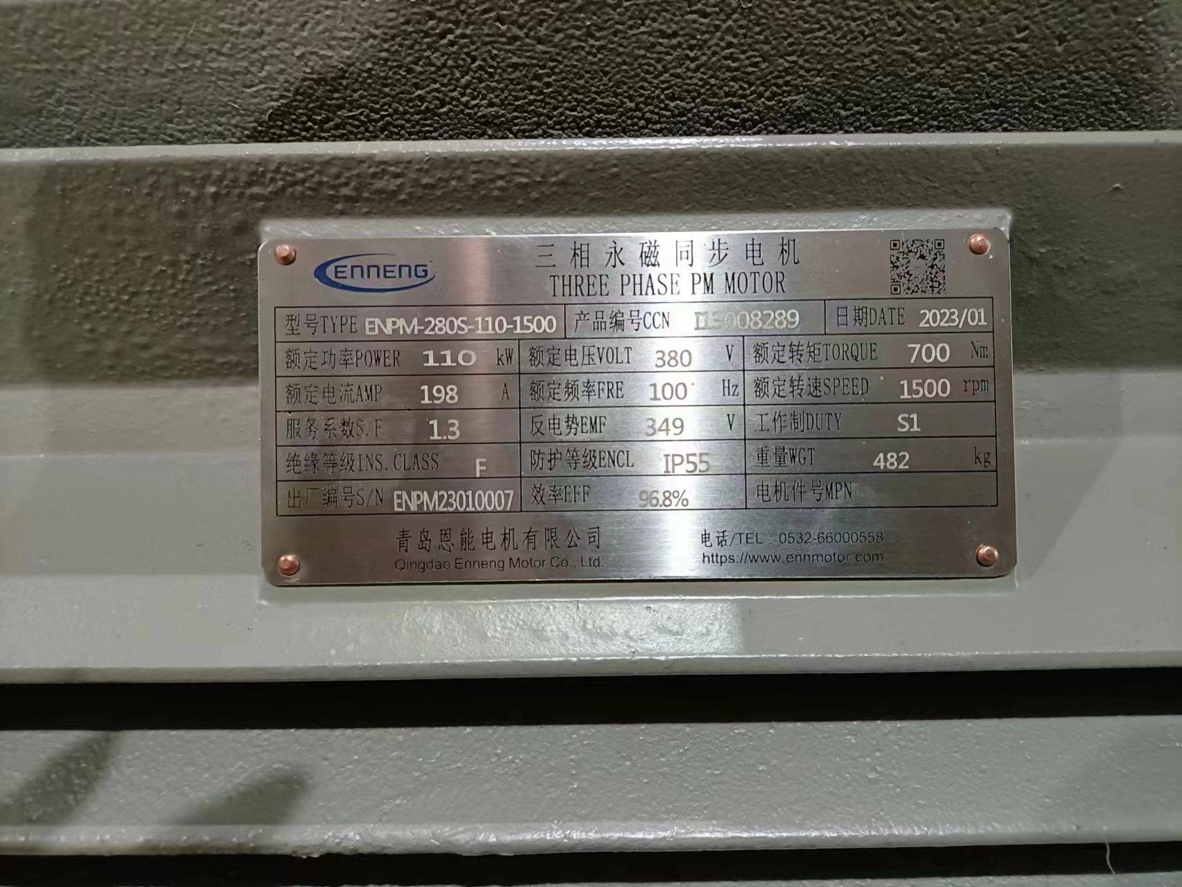
PMSM VFD compatibility is a system question, not a checkbox on a drive brochure. An inverter may list permanent magnet motors among its supported types and still be unsuitable for your actual motor, speed range, feedback arrangement or installation. Before either component is ordered, the motor supplier and drive integrator need one agreed operating envelope. The checklist below helps you assemble it.
Begin with the load, then choose the control method
Start at the shaft. What torque is required continuously, what torque is required briefly, and at which speeds? Record the machine's inertia, acceleration time, stopping method, starts per hour and expected direction changes. A pump that spends most of its time at moderate flow presents a different control problem from a loaded mixer starting at low speed. If a process needs position holding or repeatable near-zero-speed torque, say so explicitly. A generic speed range does not communicate that requirement.
Ask the drive vendor to name the exact control mode intended for the proposed PMSM. The answer might involve encoder feedback, sensorless estimation, or another supported strategy, but the correct choice depends on the motor and duty. The drive manual should identify the applicable motor type and commissioning procedure. Do not infer compatibility from its voltage or power class alone. Some general-purpose drives support several motor types only with particular firmware, options or parameter sets.
The U.S. Department of Energy's motor-system guidance treats the drive, motor and driven load as a coordinated system. Its sourcebook also cautions that variable-frequency drives are not appropriate for every application. That is a useful discipline for a PMSM project: confirm the process benefit and control need before specifying an inverter simply because one was used in a different installation.
Match electrical data at the real operating point
Provide the complete motor data sheet to the drive integrator: rated voltage, current, frequency, speed and power; pole count; winding connection; insulation information; and any parameters the drive's PMSM identification routine requires. The exact list varies by controller. Where a value is not documented, ask the manufacturer for it rather than copying it from a motor of similar size. The proposed output-current rating must cover the actual continuous and transient duty under the drive's enclosure, ambient and switching conditions.
Check the DC bus and output-voltage limits against the motor's required speed and torque. A proposed maximum mechanical speed is not proof that full torque remains available there. Above a given operating region, voltage limitation may change the control strategy and available torque. The drive supplier should review the complete torque-speed envelope, including any field-weakening operation, with the motor supplier. If the machine can be driven externally when the inverter is off, include that scenario in the electrical safety and protection review.
ENNENG's archived product material identifies a TYB standard-type family and a TYP general-type family. Those family names establish catalog context; they do not prove that every configuration has identical winding data or works with one universal inverter setting. The legacy TYP table also contains a field inconsistency, so this article makes no series-wide efficiency or frequency promise. Request a project-specific data sheet before locking the drive choice.
Review feedback, cables and protective functions
A control method that needs position feedback also needs a compatible encoder or resolver, interface card, supply, wiring and commissioning method. Specify signal type and connector details, not just the word 'encoder'. For long motor leads, review the drive maker's limits and the motor's insulation capability. Cable construction, screen termination, grounding and any output filter can affect voltage stress and electromagnetic interference. These are installation design decisions; they cannot be inferred from a motor catalog photograph.
Protection should be built around measurable limits. Agree on current, thermal sensing, overspeed, stall or loss-of-feedback behavior, and the response to a power interruption. A temperature sensor that exists in the motor but is never wired to the drive provides no useful trip. Likewise, a default current limit that happens to permit a test start may be wrong for continuous service. Ask who owns each protective setting and who signs off after commissioning.
Manufacturer-specific documentation matters here. ABB's permanent-magnet synchronous-machine drive manual is one example of a drive maker providing a dedicated control program rather than treating all AC motors as interchangeable. It is evidence for the need to check the selected drive's instructions, not an endorsement of one model for an ENNENG motor. Use the actual firmware and hardware manuals supplied for your project.
Set a commissioning sequence before shipment
Commissioning begins with a record of the as-built motor, drive and cable configuration. Verify the nameplate and motor-data entry, phase connections, grounding, feedback wiring and protective circuits before motion. The responsible engineer should then follow the drive maker's identification and tuning instructions under the permitted mechanical condition. Some identification routines are stationary; others can rotate the shaft. The machine owner needs to know which will happen.
Run the agreed functional tests from low-risk conditions toward the normal duty. Record current, speed, torque estimate, temperatures, vibration and any drive alarms at defined points. A successful unloaded spin is only an initial check. Loaded operation and thermal stabilization are necessary to see whether the proposed combination can perform the intended process duty. Keep the drive parameter backup and test log with the machine documentation.
Before acceptance, define what counts as a pass: stable speed regulation, allowable temperature, protection response and the required process output. State the measurement method and who supplies the instruments. If performance is compared with an old drive train, use the same process output and boundary for both. The ENNENG selection guide provides a broader RFQ checklist for motor, mechanical and site data.
What to send in a PMSM and drive RFQ
A short, well-structured inquiry prevents several rounds of guessing. Include the driven equipment and duty profile; continuous and peak torque at each speed; supply and proposed inverter details; cable route and approximate length; cooling and ambient conditions; mounting and shaft drawings; feedback needs; and the required test or acceptance method. Attach existing nameplates only as background. If this is a replacement, note what failed and whether the present installation has overheating, nuisance trips, noise or bearing issues.
Separate known measurements from assumptions. Label an estimated load as estimated. If torque was calculated from electrical input, explain the calculation and its unknowns. The supplier can then identify missing evidence and propose a selection review without turning an uncertain estimate into a published rating. Send the operating data when you are ready for a project-specific discussion.
Questions that deserve a written answer
Can the exact drive hardware and firmware control this motor type? What data and identification routine are required? Is the specified continuous current available at the site temperature? Does the control method meet the low-speed and transient duty? Which feedback device is supplied and who commissions it? Are cable length, filtering, grounding and insulation addressed? What happens if the load back-drives the motor? Who sets the thermal and overspeed limits, and how will those limits be tested? An answer recorded against each question is more useful than a broad compatibility claim.
Finally, keep product suitability separate from general engineering advice. The presence of PMSM capability in a drive family does not certify one particular ENNENG motor, nor does the existence of a motor series establish a match to an unspecified drive. The only defensible conclusion follows a documented motor-drive pairing and an agreed duty. That documentation should travel with the installation and be revised if the motor, inverter, firmware, cable or driven process changes.
Sources and evidence boundary
General drive-system guidance: U.S. Department of Energy, Motor Systems and Improving Motor and Drive System Performance. Drive-specific example: ABB Permanent Magnet Synchronous Machine Drive Application Program. ENNENG family references derive from the archived TYB and TYP product pages; current parameters require manufacturer confirmation.