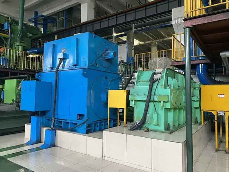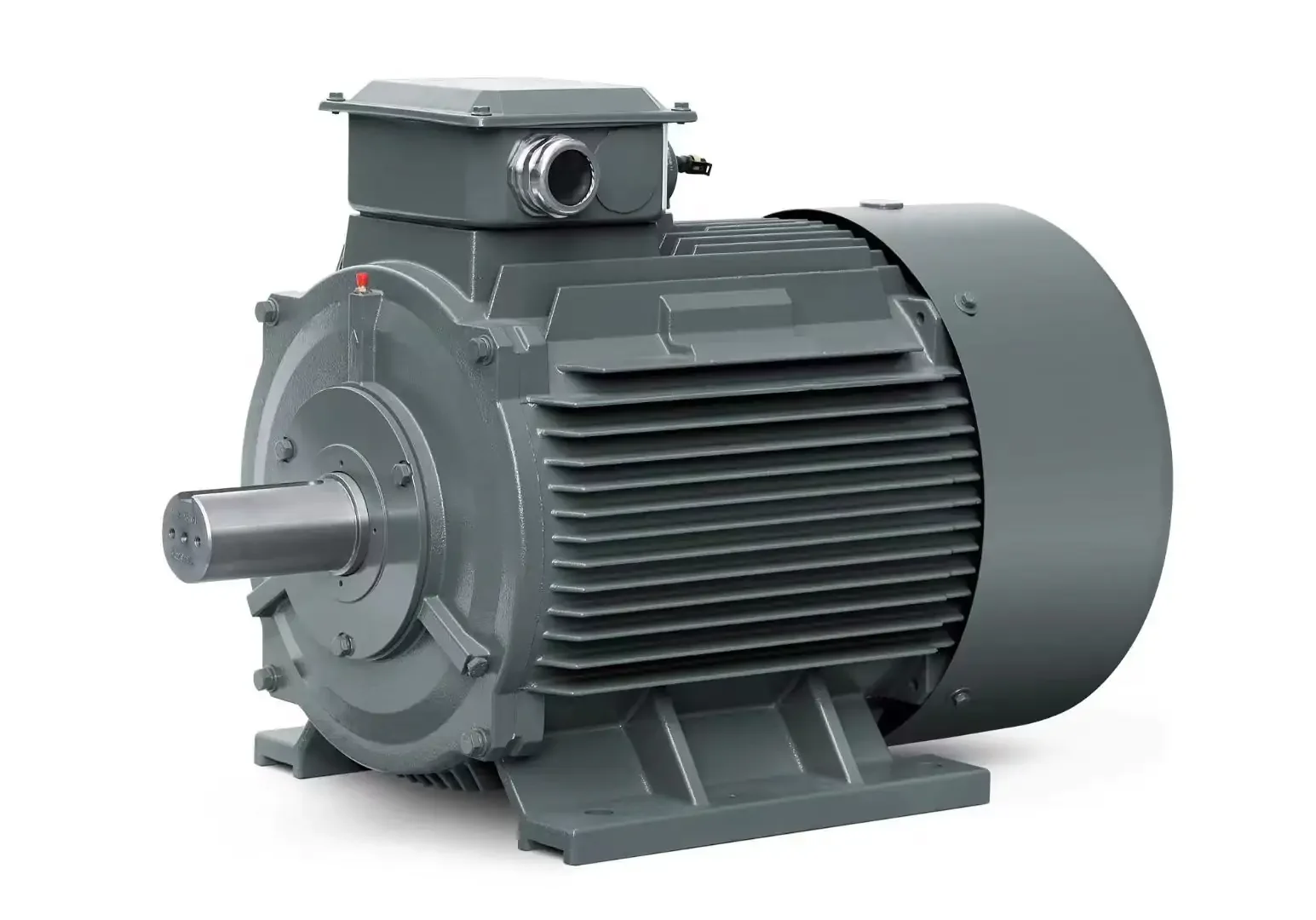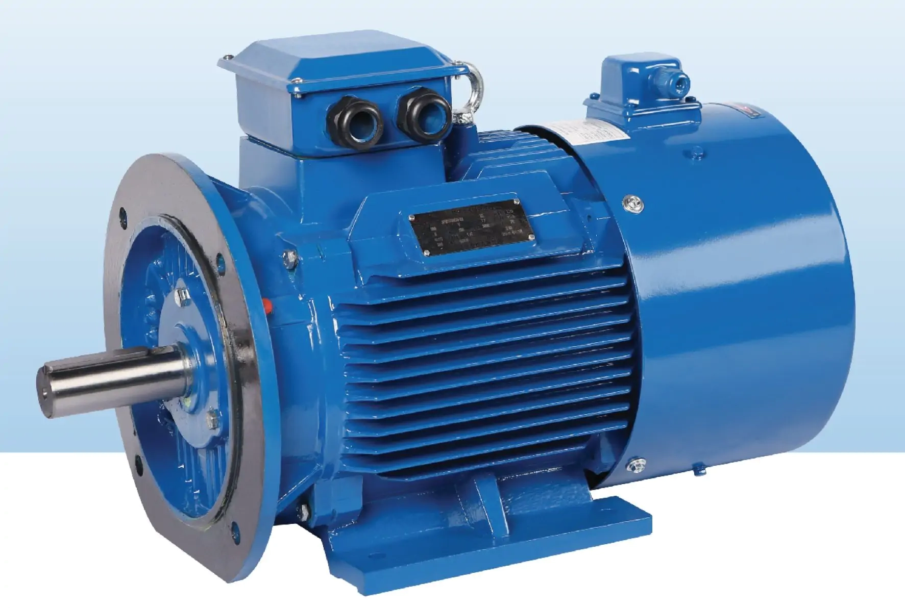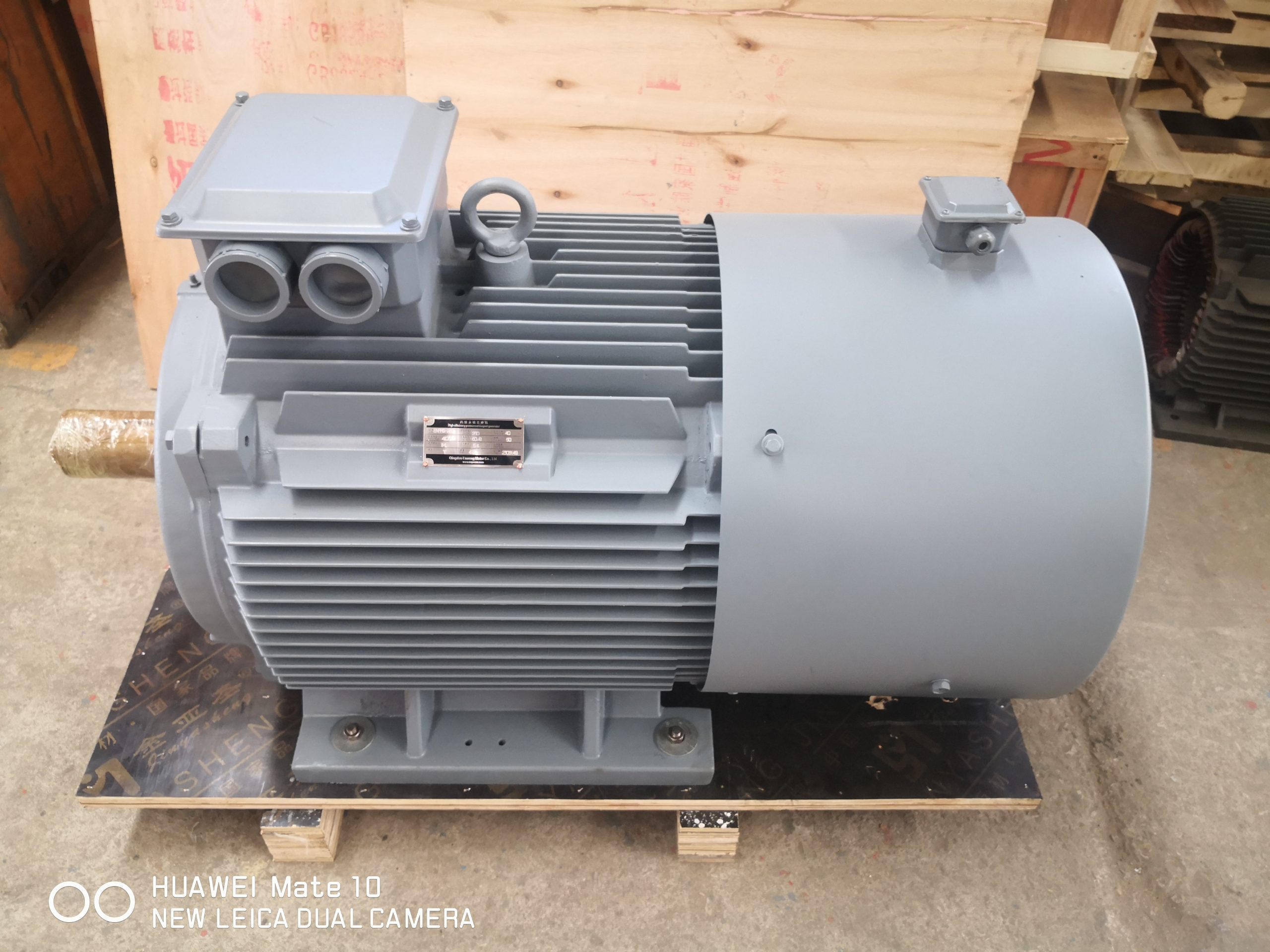
PMSM cooling at low speed becomes a design question when a machine must hold substantial torque while turning slowly. The motor may meet a nominal power figure and still run too hot at the point that matters to your process. An output shaft that turns more slowly can reduce airflow from a shaft-mounted fan. At the same time, a high-torque load can keep current and heat substantial. You need the thermal duty at the actual operating points, not a promise based on peak torque.
Separate continuous torque from a short peak
Ask first how long each torque demand lasts. A mixer may need a high breakaway torque for a short start and a lower running value. A conveyor might face a brief loaded restart but then settle into a predictable continuous load. A slow indexing machine can reverse often, with heating during acceleration and braking that a steady-state calculation misses. The same maximum torque number can describe all three machines while implying very different thermal requirements.
Write a duty table with shaft speed, torque, duration, start frequency, direction changes and time spent stationary but energized. Mark continuous operation separately from intermittent events. A motor's torque-speed curve should state the cooling and ambient conditions under which it applies. Where a proposed low-speed operating point sits outside a documented continuous zone, ask for a validated thermal calculation or test rather than assuming that a short-duration peak can be held indefinitely.
The U.S. Department of Energy's motor and drive sourcebook describes poor cooling as a possible problem when reducing speed, especially where load torque does not fall with speed. It discusses externally powered fans as one response in some applications. That general principle is useful, but it does not identify the correct cooling arrangement for a particular ENNENG motor. The manufacturer's configuration and site duty still decide that.
Understand where heat goes at reduced speed
Motor heat arises from more than one source: winding loss, iron loss, mechanical loss and additional effects associated with the inverter and installation. Their balance changes with speed and load. The heat must then move from the internal components through the frame and cooling medium into the surrounding environment. A ventilation path that works at rated speed may not move enough air at a slower point if the fan is driven by the same shaft.
Do not make the opposite mistake either. Low speed is not automatically the worst thermal point. A variable-torque fan or pump may require much less load at reduced speed, depending on the system curve and control method. Compare actual shaft torque and current at each point. If the driven process retains near-constant torque or demands frequent acceleration, cooling may remain a central constraint. The right conclusion follows a duty-cycle calculation and temperature evidence, not from the word 'low-speed' alone.
Ask whether the proposed unit is self-ventilated, separately ventilated, liquid-cooled or designed with another thermal path. If an independent fan is included, specify its electrical supply, airflow monitoring or failure response and maintenance access. For liquid cooling, define the flow, temperature, pressure, water quality and leak responsibilities in the project design. The cooling auxiliary itself belongs in any system-level efficiency comparison.
Use product-family information carefully
ENNENG's legacy pages list a TYB standard-type permanent magnet motor and a TYP general-type permanent magnet motor. Those pages provide family identities, not permission to apply one cooling or rating table to every custom operating point. The archived TYB material has an efficiency-grade conflict, and the TYP table has a field mismatch. Neither issue changes the basic need to identify the exact proposed unit and obtain its controlled data sheet.
When comparing catalog candidates, keep power, speed, cooling method, duty and ambient conditions together as one record. A row from one group cannot be combined with a speed or cooling condition from another and presented as an available product. For a nonstandard speed range or installation, ask the supplier which configuration is being proposed and which values remain to be verified. The PMSM product overview is a starting point for that conversation, not a substitute for a project-specific specification.
State the site environment and physical constraints
Ambient temperature, altitude, dust, humidity, washdown and proximity to hot process equipment all influence thermal design. So do installation orientation, enclosure space and blocked airflow. A motor inside a tight machine housing may receive its own warm exhaust air. An external cooling fan can be physically present and still underperform if intake and discharge paths are restricted. Share photographs and a layout drawing alongside the electrical requirements.
The drive installation affects heating and protection too. Supply quality, cable length, switching settings and the control method can change electrical stress or losses. Review them jointly with the drive maker rather than treating the motor's cooling drawing as an isolated solution. ABB's permanent magnet motor installation documentation, for example, calls attention to ventilation and environmental conditions; it is an illustration of the type of manufacturer instruction to follow. Its limits are not transferable to a different motor.
Specify temperature sensing before the wiring design is finalized. Determine which sensors are fitted, what they measure and how the drive or supervisory controls respond. An alarm, derating action and trip should have clear thresholds and owners. If cooling depends on an auxiliary fan or pump, establish what happens when that auxiliary loses power while the main motor is still commanded to produce torque.
Check the complete speed and torque envelope
Do not qualify a motor on one slow point and ignore the rest of its duty. Plot the required continuous and transient points from minimum to maximum speed. Include field-weakening operation if the machine reaches a voltage-limited region. Review bearing loads, vibration, critical speeds and the driven equipment interface separately from thermal performance. One verified low-speed torque point cannot establish safe operation at every speed.
Where a retrofit is involved, record actual process output and electrical input before removing the old system. If possible, collect motor current, speed, ambient temperature, duty history and temperature trends during a representative production period. Existing thermal problems can reflect mechanical overload, poor ventilation or control settings rather than a motor family alone. Preserve those observations; they help suppliers distinguish the required duty from symptoms of an unhealthy installation.
Compare proposed alternatives at the same boundary. A larger self-ventilated motor, a smaller motor with independent cooling, and a different transmission may all meet the shaft requirement. Their auxiliaries, packaging, maintenance and control needs differ. The strongest proposal explains how each relevant operating point remains within a documented continuous or transient limit and how the cooling system will be maintained.
Turn thermal assumptions into an acceptance test
Set the test condition before purchase. Identify the actual load or a justified equivalent, ambient condition, operating sequence, sensor locations, data-logging interval and stabilization criterion. Record current, speed, torque or process proxy, and winding or frame temperature as available. A brief no-load run can verify rotation and wiring, but it cannot demonstrate continuous low-speed thermal capability.
Factory testing and site testing answer different questions. The factory may control input conditions and measure the motor under a defined load. The site test includes the actual ventilation path, enclosure and process cycle. If both are required, state what each must prove and how a difference will be investigated. Keep a signed record of the installed cooling configuration and drive settings so a future change does not silently invalidate the accepted operating envelope.
The RFQ should include a duty table, environmental conditions, cooling preference or constraint, inverter details, mechanical drawings and the proposed acceptance method. Use the selection checklist to gather the surrounding motor and drive information. If essential data are missing, label them as open measurements. A supplier can help plan how to obtain them; it cannot turn an unknown peak duration into a reliable continuous rating.
Practical questions for the engineering review
At what low-speed point is continuous torque required? How long does the machine remain there? What starts, stops and reversals occur in the same cycle? Is the proposed fan tied to the shaft or powered independently? What happens after loss of cooling? Which sensor protects the winding, and which device acts on its signal? What ambient and enclosure conditions were used for the published rating? Which points will be demonstrated in a witnessed test? Written answers to these questions create a useful thermal specification.
A final caution: 'permanent magnet' describes the rotor field; it does not remove winding loss, thermal limits or the need to cool a heavily loaded machine. Treat any claim of unlimited low-speed torque as incomplete until its duration, temperature rise, cooling method and acceptance boundary are stated. Send the duty schedule and site constraints for a configuration review rather than choosing on a single headline number.
Sources and evidence boundary
General motor-system thermal discussion: U.S. Department of Energy, Improving Motor and Drive System Performance. Manufacturer instruction example: ABB, Drive Low Voltage Permanent Magnet Motors installation, operation and maintenance manual. The TYB and TYP family identities are traced to ENNENG's archived product pages; no model-specific rating is asserted here.