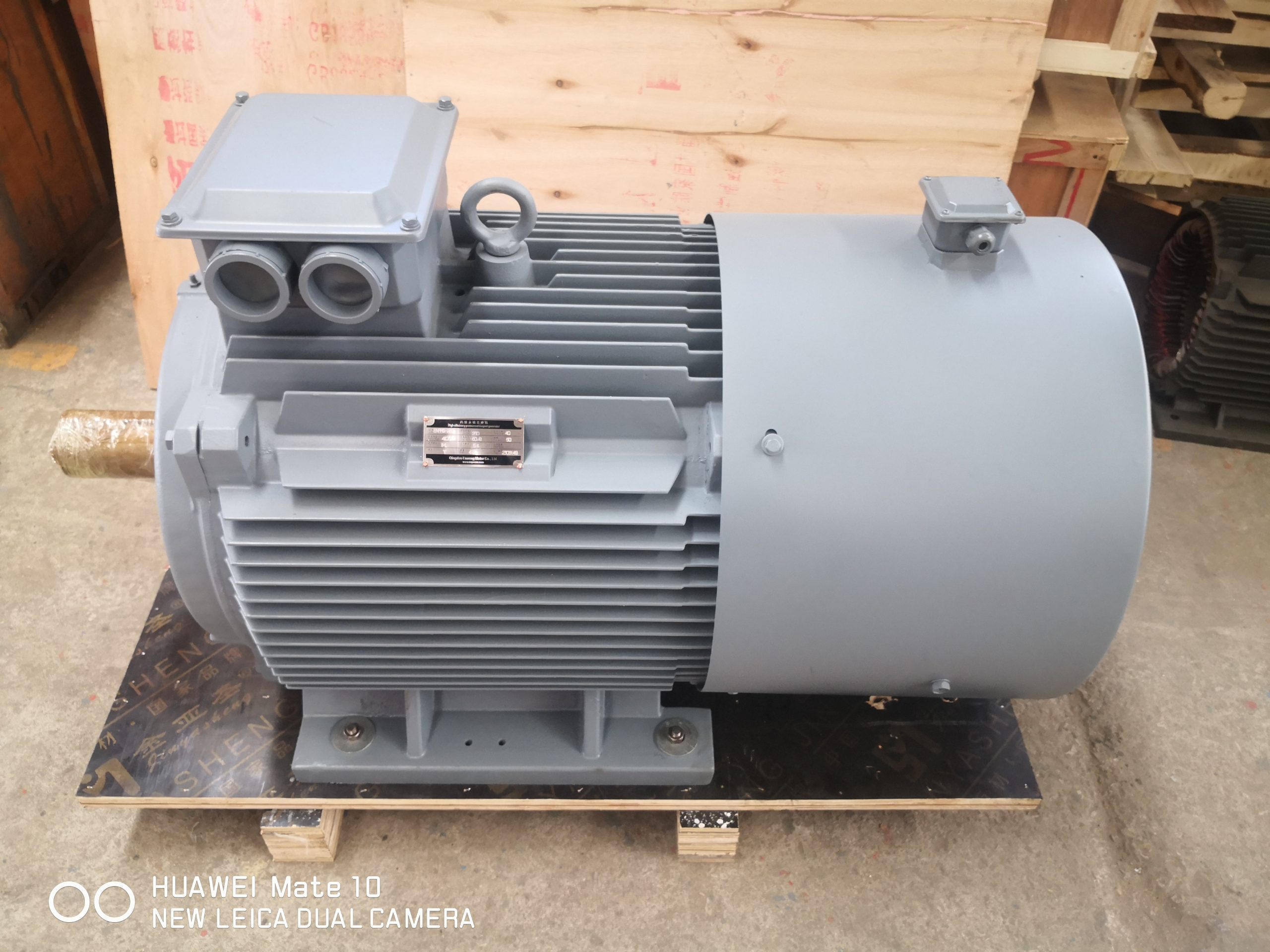
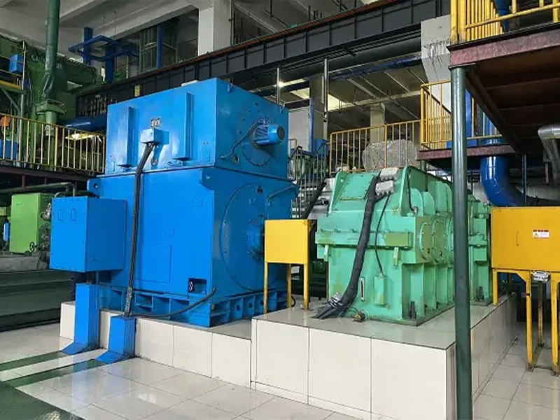
Begin with the driven system
A permanent magnet motor project should begin with the machine being driven, not with a nameplate copied from another installation. Record the required shaft power, normal and maximum torque, operating speed range, acceleration time, starts per hour and the amount of time spent at each load point. Pumps and fans often follow a variable process demand, while compressors and production machines may introduce different starting or transient requirements. These differences change the correct motor, drive and control discussion.
The boundary of the comparison also matters. A motor-only efficiency figure does not describe losses in the variable-frequency drive, transmission, coupling or driven machine. The U.S. Department of Energy treats motors as part of complete motor-driven systems for this reason. A useful proposal therefore states which components are included, which duty points were evaluated and which assumptions still need site confirmation.
How a PMSM produces torque
In a permanent magnet synchronous motor, magnets on or within the rotor establish the rotor magnetic field. The stator windings create a rotating magnetic field, and the rotor follows that field in synchronism under controlled operation. Because the rotor field does not need to be created by induced rotor current, rotor excitation losses associated with an induction rotor can be avoided. This operating principle is relevant to efficiency and power density, but it does not make every PMSM equally suitable for every duty.
Rotor topology, magnetic loading, winding design, cooling, enclosure, bearing arrangement and control strategy all influence the usable operating envelope. Surface-mounted and interior magnet arrangements can behave differently at speed and under field weakening. These are engineering choices rather than labels to rank in isolation. ENNENG needs the target speed-torque curve and supply conditions before discussing a suitable series or a tailored design.
Motor and drive must be selected together
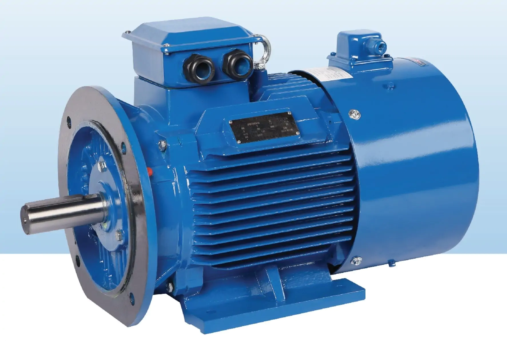
A PMSM normally operates with an electronic drive that controls stator current and electrical frequency. The drive must support the motor type, voltage, current, switching strategy and feedback method required by the application. Low-speed torque, rapid reversals, wide constant-power operation or tight process regulation can change the need for an encoder and the required control mode. Confirm those requirements before fixing the drive architecture.
Cable length, grounding, bearing-current mitigation, electromagnetic compatibility and protection settings also belong in the design review. A mechanically suitable motor can still perform poorly if the drive is not commissioned with correct motor data or if the installation creates unacceptable voltage stress. The inquiry checklist on this site asks for system information so motor and drive questions are resolved in the same technical exchange.
Thermal duty defines usable output
Rated power is meaningful only with its associated speed, cooling method, ambient temperature, altitude and duty cycle. Continuous operation at one point imposes a different thermal load from intermittent peaks. At reduced speed, a shaft-mounted fan may move less cooling air, while frequent acceleration adds current and heating. The thermal model should reflect the real cycle rather than a single headline power value.
Share ambient conditions, dust or moisture exposure, installation orientation and any restrictions on ventilation or liquid cooling. If the motor sits near a hot process or inside an enclosure, include that information. These details help define temperature margin, insulation requirements, sensor needs and protection logic. They also prevent a nominally correct rating from being applied outside the conditions under which it was established.
Mechanical integration is part of selection
Frame dimensions alone do not prove interchangeability. Check shaft diameter and extension, key or spline details, flange register, foot position, coupling arrangement, radial and axial loads, balance requirements and the natural frequencies of the coupled system. For replacement work, provide the existing motor drawing and clear photographs of the base, shaft and connection area.
Alignment and foundation stiffness influence bearing life, vibration and coupling behavior. The Department of Energy motor guidance includes shaft alignment among practical motor-system concerns. A replacement plan should therefore include alignment tolerances, soft-foot checks and a baseline vibration record. If a different rotor inertia changes acceleration or torsional response, the driven machine and control sequence may also need review.
Compare performance at real duty points
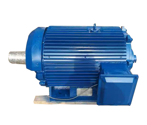
A sound comparison uses a duty profile rather than one best-case point. List the expected hours at each speed and load, then evaluate input power across that profile. Include drive and transmission losses when they differ between alternatives. This reveals whether an efficiency advantage occurs where the process actually operates and prevents a peak figure from being mistaken for annual performance.
Also compare power factor, starting behavior, overload needs, cooling auxiliaries and maintenance tasks. If the project is a retrofit, measure existing electrical input and process output before making claims about savings. Baseline data should be collected under comparable production conditions. ENNENG can discuss equipment configuration, but project savings must be calculated from site data and verified after commissioning.